ATX PSU to Bench-top PSU

Mini ATX PSU for all development and ancillary power needs
In this blog I will give a brief overview of a recent basic project to convert a surplus mini ATX PSU in to a handy bench-top power supply that has many uses. These include power for electronic project development, an ancillary supply for IT peripherals and a super high current supply for Raspberry Pi computers and projects. The later was the main reason for repurposing this unit as I need a fairly hefty and very stable PSU to run my RasPi’s which also boot from USB SSD drives powered via the Pi’s USB3 bus. The PSU is also useful for powering digital audio peripherals and I have used it to run my Focusrite USB audio interface which requires 12V at 2A.
First a word of caution
Computer PSU’s are inherently dangerous devices. They are switch-mode mains voltage power converters with no galvanic isolation (input transformer). Internally they have many exposed live parts and also contain capacitors that can be charged to lethal voltages even days after the device has been switched off. This means that any work on an ATX PSU should only be undertaken by an electrically competent person. DO NOT ATTEMPT TO OPEN OR MODIFY AN ATX PSU UNLESS YOU UNDERSTAND HOW TO MANAGE THE RISKS and any work is strictly undertaken at your own risk!
ATX Colour Codes
A recap on the ATX colour codes. This is obviously vital information and before starting any conversion project it is important to know how to re-utilize the large wire loom.
Most modern ATX PSUs will either have a large hard-wired harness (bulk of wires coming out) with various connectors on the end including the main connector for an ATX MOBO. However, some of the more expensive top-end PSUs have detachable wiring or plug in harnesses. Generally, it is easier to work with the cheaper models that have a soldered-in wire harness.
ATX PSU colour codes
|
Black |
0V (GND) |
|
|
Orange |
3.3V | |
|
Brown |
3.3V Sense |
Thin wire, must be connected to one of the orange wires. Some PSUs will not start if this connection not made.
|
|
Red |
5V | |
|
Pink |
5V Sense |
Thin wire, must be connected to one of the red wires
|
|
White |
-5V |
Not used : obsolete
|
|
Yellow |
12V | |
|
Blue |
-12V |
Thin wire – not used
|
|
Green |
Activate |
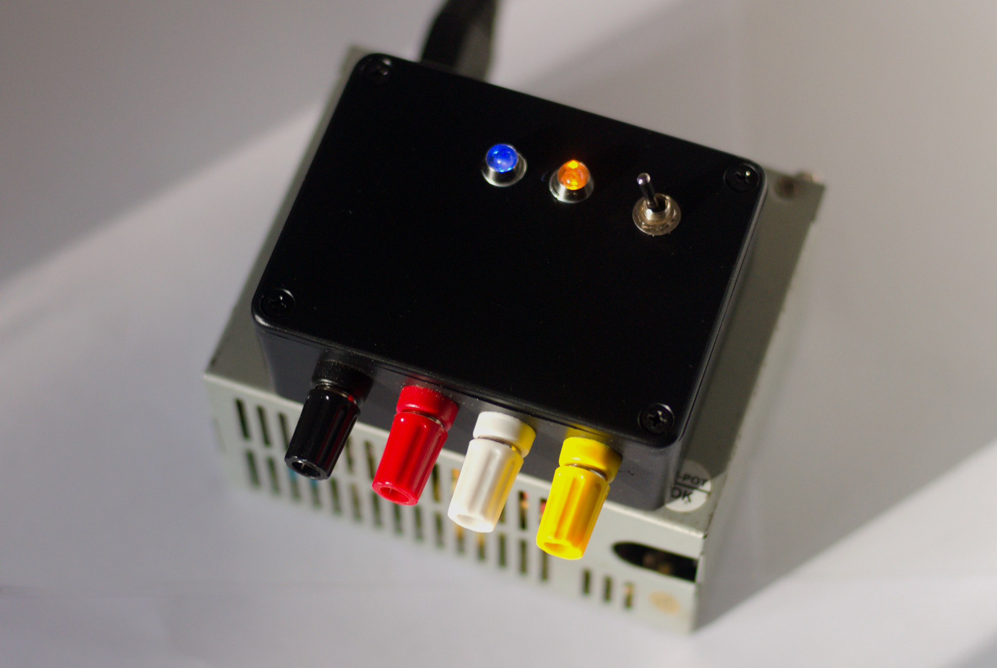
Thin wire turns on PSU when connected to GND (toggle switch on my build)
|
|
Gray |
Power good |
Thin wire goes to +5V with respect to GND when PSU is active (yellow LED on my build)
|
|
Violet |
Standby |
Thin wire at +5V with respect to GND when PSU is connected to mains (blue LED on my build)
|
On a PSU you will notice that there is a lot of duplication in the wire harness – you will have multiple red, yellow, orange and black wires, this allows very large currents to be distributed in a multi point circuit architecture rather than having massive single power rails. Some ATX PSUs are capable of delivering more than 20 Amps at 5 and 12 Volts!
When constructing your bench-top PSU you may only need to use two of each of the main voltage bus wires or three or more. This all depends on the intended current delivery or load of your system. For my build the demand is expected to be relatively low, no more than 5 Amps so I have used three wires for each of the voltages. 3 red 5V, 3 orange 3.3V and 3 yellow 12V. I set aside 4 black 0V (GND) wires – three for the 0V GND connection and one for the ancillary items such as the operate switch, standby and power good LEDs.
Making it
The mini ATX case is very small and cramped inside, there was no safe internal space for any intrusions so I decided to go for a rather novel approach and mount my connectors and controls in a retrofitted plastic box. A large hole (20mm diameter) was cut in the top of the PSU case and the bottom of the plastic box for all of the wires which previously exited the ATX case at the rear.

As I mentioned previously, I only needed to have three of each set of wires (Red, Orange, Yellow, Black) plus the brown sense wire for 3.3V and green, gray and violet wires for ancillary controls. There was no pink 5V sense wire on this PSU.
I have connected the wires to some nice binding posts (white is used for 3.3V because these things don’t come in orange). The green activate wire was connected to ground via the switch to turn on the PSU from standby state. The purple (violet) wire and GND was connected to a blue LED and the gray power good wire and ground was connected to a yellow LED.

This is actually my third ATX PSU mod and the other two are both on full size modules where I have mounted the connectors, lights and switches into the existing box but I think this new method of using a retrofitted box on top is better.
A note on fans
In this particular build I have left the fan permanently in circuit as it is so quiet. However, I have other modified ATX based PSUs where I have put a switch in the fan circuit for quiet running when used in a audio (recording) context. This is OK so long as the PSU is operating at less than 20% of its maximum demand and very unlikely to have any heat issues.
« Bashrc Linux – a guide | Linux Lightweight Distro Reviews »
Prestburyweb